Wire EDM machines use a small, traveling wire electrode to machine complex shapes, which are always through cavities (the wire must pass completely through the workpiece). Machines are capable of cutting and re-threading the wire automatically, which greatly extends unattended machining time. All newer machines operate fully submerged under a filtered water dielectric fluid, and high-pressure flushing is used to remove debris from the spark gap area.
The Wire EDM process is similar to a band saw that’s used to cut wood, metal or plastic. A long, thin copper or brass alloy wire rolled on spools replaces the saw blade to remove material. That’s where the similarity with conventional machining ends, however, because in EDM processing, the wire never touches the workpiece.
During operation, the wire electrode originates from a main spool and travels over a series of rollers where precise tension is applied to the wire. The wire travels through the workpiece (where EDM machining occurs) being guided by two precision alignment wire guides and is then routed into a collection basket in the rear of the machine. The wire is only used once because the discharge machining process erodes and reduces the size and shape of the wire. Once it’s been used, the wire is no longer perfectly round. Due to the constant and continual renewal of the wire electrode, achieved level of precision is maintained.
Wire EDM machines are capable of operating with a range of different wire diameter sizes. The most common size range is from 0.004” to 0.012” Ø (0.100~0.300mm), and the most widely used wire size is 0.010”Ø (0.250mm), but there are some machines that are capable of operating with wires as small as 0.0006”Ø (0.015mm). Changing the wire size provides one of two benefits. First, a smaller diameter wire will produce a sharper inside corner radius. Second, a larger diameter wire will provide faster roughing machining speeds, as the larger cross-section of the wire will allow and withstand higher EDM discharge energy without breaking. There is a physical limit to how much power can be applied to and sustained by any given wire size before the wire (think of it as a small filament) melts, breaks, or fractures.
Reliable operation of Wire EDM machines is strictly dependent on several operational maintenance items. By design, Wire EDM machines are electro-mechanical systems that require precise function of all components to be productive. Like a chain being only as strong as its weakest link, Wire EDM machines are only reliable as the amount of maintenance that is performed.
Wire EDM machines do require a significant amount more maintenance and continuous TLC than other conventional machines such as lathes or mills. From a maintenance standpoint, the key difference with Wire EDM Maintenance is that it is performed as a proactive and preventive measure before the machine encounters a failure. Following the Wire EDM’s recommend maintenance intervals ensures reliable operation and prevents the loss of productive unattended machining. Maintenance items that are typically performed are primarily cleaning of the rollers, precision wire guides, and indexing of electrical contacts.
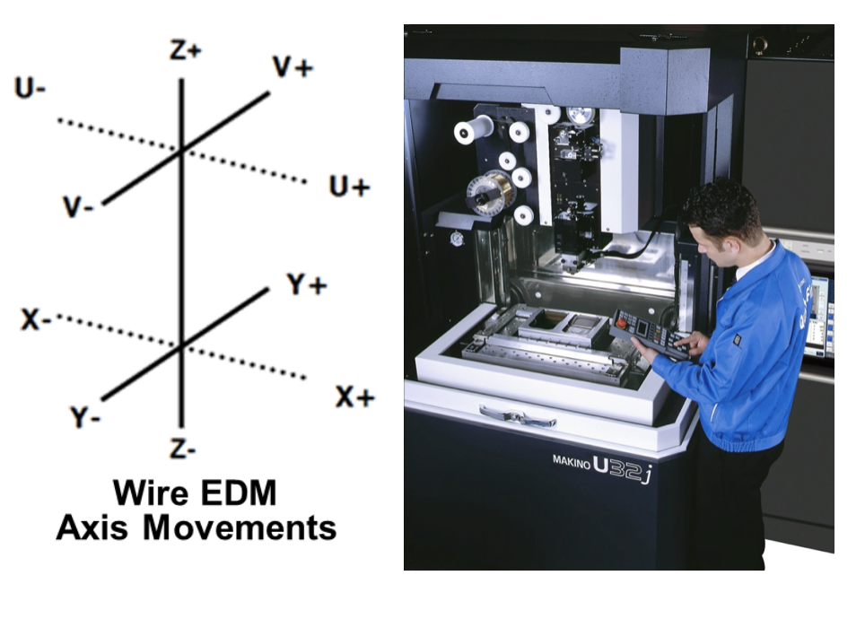
The vast majority of Wire EDM parts are cut straight, but some may include tapers and varying angles. Most Wire EDM machines contain 5 axes, but only 4-axis simultaneous machining is possible (Z-Axis remains stationary during machining). The machine axis layout consists of a typical X/Y/Z configuration, but there is also a U/V axis that is parallel and stacked on top of the X/Y axis. The movement of the U/V axis tip or tilt the wire at different angles to produce tapers, but the wire will always follow a straight linear path that is at an angle. Machines can also be equipped with additional 1- or 2-axis rotary tables that enable access to multiple sides of a workpiece in a single setup.
The maximum part size that can be machined by Wire EDM is dictated by the capacity of the X/Y/Z strokes, the size of the work tank, and the weight capacity specifications of a particular machine. The most popular machine size provide a 14” x 10” X/Y stroke with an 8”~10” Z-stroke capacity, and support part weights in the range of 1,000~1,500 lbs. The U/V axis strokes also determine what the maximum taper angle at a specific workpiece thickness can be machined. Most machines support taper angles up to 15 degrees, but there are special wire guides that allow angles up to 45 degrees.
Programming a Wire EDM shares many parallels to 2D Milling; however, the program start location is commonly at the center of a pre-drilled hole. Wire EDMs require an NC G-code program for the shaped geometry. This format is identical to that found in Milling (G90, G91, G00, G01, G02, G03). Differences are found in the M-code commands, as Wire EDMs have many specialty M-codes that are specific to Wire EDM operations, such as threading and cutting of the wire. The most efficient method for Wire EDM programming is using a dedicated software module designed for Wire EDM operations, as this will provide many helpful and time-saving processing tools for Wire EDM that cannot be performed using software designed for milling.
The workpiece setup in a Wire EDM requires that the part be suspended out within the confines of the work zone. Parts can be bolted directly on the outer perimeter work table, but the feature requiring machining must be suspended out into the working stroke area. Special tooling vises are also used to hold parts upward of 40 lbs. These also provide an easy adjustment method to level and align the part within the machine. Once a workpiece is physically setup in the machine, operators commonly check and verify the part alignment and flatness within the machine using a dial test indicator. Then the final workpiece origin is set by using a canned pick-up cycle in the machine that uses the wire with touch sensing to find part centers or edges. Some machines can also utilize CMM-style probe systems to find start locations and for 3D part leveling.
The biggest expense in operating a Wire EDM is the spent wire. The consumed wire spools are purchased on pre-wound reels that can vary in capacity, but 11- and 22-pound spools are the most common. Many machines today have improved and reduced the amount of wire consumption, and the more efficient machines consume 0.5~0.6 lbs. of wire per hour running 0.010” Ø. Older or less-efficient machines will consume over 1 lbs. per hour. There is a hidden recycling bonus at the end to where the spent brass wire can be sold to a local scrap metal recycler.
Wire EDM machines also entail other consumable wear items that require periodic replacement and care such as filters, DI resin, wire guides, energizer contacts, rollers and bearings, as well as additional items. Beyond understanding the necessary consumable elements, Wire EDMs encounter machine downtime while these items are tended to during machine maintenance. This can include disassembly and cleaning of many components and re-calibration of the machine before being put back into production. The amount and type of required machine maintenance and consumable wear items can vary greatly between the different Wire EDM OEMs and should be an evaluation factor when looking at new equipment. From an operating standpoint, the more efficient Wire EDM machines will have a per-hour operating cost of around $4.00.
Wire EDM had its founding and initial use in the 1970s in die/mold applications; machining details such as dies, punches, inserts, etc. for stamping and plastic injection tooling. Wire EDM revolutionized this industry in how these tooling components were made, as prior to Wire EDM, many complex hardened tool steel components required very time consuming and difficult segmenting and grinding to be made. Wire EDM has grown and expanded to include many more industries that rely upon this unique machining method to produce high accuracy details. Wire EDM is commonly seen today in high- or short-run production applications, such as parts for the medical and aerospace industries.
The most common type of processing performed on Wire EDMs is 1-, 2- or 3-pass machining. Anything beyond 1 Pass (rough cut) machining is referred to as a skim or trim cut, and each consecutive pass improves both part accuracy and surface finish. A 1-pass process typically achieves a tolerance of ±0.001 (±0.025mm) and a surface roughness of 120µinRa (3.0µmRa), a 2-pass process achieves tolerances of ±0.0005” (±0.012mm) and a surface roughness of 70µinRa (1.8µmRa), and a 3-pass process achieves tolerances of ±0.0002” (±0.005mm) and a surface roughness of 25µinRa (0.6µmRa). These processing values are strictly for general expectations and guidelines, and can vary by application and by machine.
As workpiece materials become harder to machine by conventional methods or the detail size becomes small with higher L:D (length to diameter) ratios, Wire EDM becomes a more attractive method of machining. Most modern machines are capable of achieving accuracies in the range of ±0.0002” (±0.005mm), but high accuracy machine models are available that are provide finer tolerances. Many high-end machines are capable of achieving finer surface finishes down to 4µinRa (0.100µmRa) or finer and can produce accuracies at or below 1 micron (0.00004” or 0.001mm).
Stay Tuned for More!
If you’ve enjoyed this third lesson in our 6-part Back to Basics series, be sure to stay tuned for future segments as we reflect on our industry and celebrate the building blocks that have led us to the fascinating EDM advancements that we encounter each day.