In an earlier Expert’s Corner (Understand Wire EDM Gear Form Machining – EDM Today Summer 2017), gear and involute geometry were examined along with the methods and capability that can be produced by Wire EDM. In this issue, we’ll explore Sinker EDM Gear Form Machining.
But first, we’ll reexamine the uniqueness of gear form geometry.
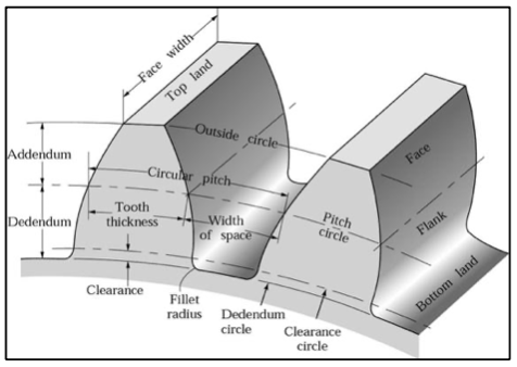
Gear Form Geometry
For starters, gear and spline details have a highly specialized geometry that transfers rotary torque motion—a mechanical advantage. Of the different gear types, Involute Gears are the most commonly produced. These arrange gear teeth in a circular configuration so that inner-connected gears can rotate together without locking. Each gear tooth, called a spline, has a precise, constantly changing arc that establishes a moving single point of contact and clearance when two gears are paired and rotated together.
The Spline geometry varies based upon application and use, and their geometry callouts may require some additional reading to understand. A few of the key terminology callouts used in involute gears include the Pitch Diameter, Circular Pitch, Diametrical Pitch, Pressure Angle, and Roll and Flank value.
The Sinker EDM process can produce both straight-wall and true radial gear forms. The most simplistic process will be creating straight-wall gears, but orbiting pattern techniques and process methods help maintain the desired geometry radii size. The use of circular orbit patterns will be the safest choice, but the orbit amount must be taken into account. The greater the orbit value, the more it will change the final produced radii size of the geometry. The drawback in using any orbit pattern on gear and spline details is that the geometry contains many different radii with varying center points, so a common or sufficient orbit method isn’t possible without altering the final geometry shape.
If high accuracy is desired on straight-wall spline gears, you’ll need different sized electrodes for Rough and Finish operations. The Finishing electrode will have a smaller electrode reduction amount and will be closer to the final target net-shape geometry, so the final results will have less distortion. It might also be necessary to adjust and slow down the orbit speed to finish gear forms with more precision and consistent surface finish results. The electrodes for straight-wall spline gears are most commonly produced by Milling or by Wire EDM depending on detail size. Internal gear forms require a punch-like electrode to be made, while external gear forms are usually made from a plate electrode.
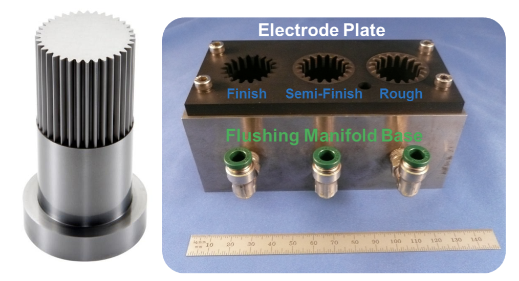 Image 1: Example of External Gear Form Part and Electrode. The Electrode contains (x3) different sized cavities for Rough, Semi-Finish, and Final Finishing. (Courtesy of MAKINO Inc.)
Sinker EDMs Can Produce Radial or Helixed Gear Forms
Unlike Wire EDM, Sinker EDM machines can produce true Radial or Helixed Gear Form details. The reason for this is pure physics. The Sinker EDM C-Axis provides the synchronized rotary interpolation that creates a radial geometry by allowing rotation of the electrode during machining. The Wire EDM process isn’t capable of producing radial forms, because the wire electrode can’t rotate.
In creating a true radial gear form, a Sinker EDM will utilize (x2) axes that are controlled together simultaneously to produce a precise radial twist. These programs most often use the combined positioning of the C & Z Axes together to produce a radial form (the electrode is rotated). It’s also possible to produce helixed geometry using X & C Axes together in a similar method to Roll-Forming (the work piece is rotated), but the electrode design requirements are different.
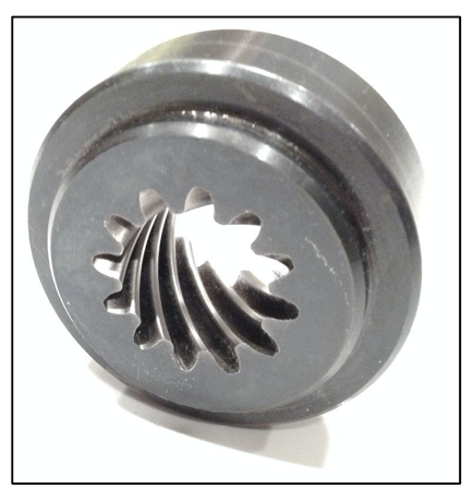 Image 2:
Helical Gear example machined using a C & Z Axis synchronized process on a Sinker EDM. (Courtesy of Bud Guitrau)
Image 2:
Helical Gear example machined using a C & Z Axis synchronized process on a Sinker EDM. (Courtesy of Bud Guitrau)
Best Practices for Producing Helical Gears
Producing helical gear parts does present some additional hidden challenges that might not be obvious to the casual observer. Because of the simultaneous and rotated nature of the machining motion (Z & C Axis machining), traditional 2D orbiting methods can’t be used. If orbiting is used on a helical gear, the electrode will cut into and damage the geometry by producing flats. It will also wipe out the helical form.
One technique you can use to finish a helical gear and maintain accurate geometry is to produce different sized electrodes. Instead of orbiting, you can use the different sized electrodes to establish a method of sizing and geometry form control. Each Finish Electrode will start from the top of the work piece and will machine down using the required synchronized twist of C/Z axis machining. This will produce a longer cycle time. since only the leading frontal edge of the electrode is in contact with the work piece. It may be advantageous to use more than one Finish electrode with different reduction amounts to help improve cycle time, because machining with too small a reduction will extend cycle time and increase electrode wear.
When using different electrodes to machine helical gears, the setup and C-Axis timing of the Rough and Finish electrodes is critical to maintaining accuracy. If there’s any error in the clocked timing between the electrodes, it will result in geometry form error on the final part and will extend cycle time. Depending on the thickness of the critical detail of the work piece, it is possible to create a single electrode that contains the geometry for both Rough and Finish machining. This method requires proper planning and design of the electrode, as the rotational timing of the electrode is uniform throughout, and the geometry size and reduction amount will be different between the Rough and Finish profile. There must also be proper clearance and spacing between the Rough and Finish electrode profiles that is greater than the thickness of the work piece detail, so that different power settings and overburn values can be used without damaging the work piece. With this method, the machining process with be a continuous C/Z axis machining motion that will apply different power levels between the Rough and Finish profile.
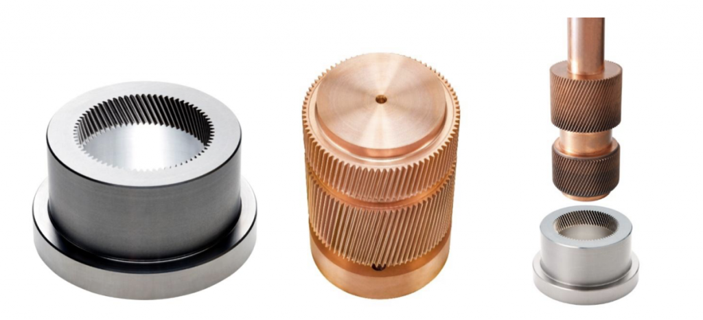 Image 4: Example of Helical Gear produced using X & C synchronized machining with a special electrode that contains profiles for Rough and Finish machining. (Courtesy of MAKINO Inc.)
Best Practices for Power Settings
The selection of power settings and electrode reduction can also represent a challenge when machining gear forms. The power settings should be determined by first taking the frontal discharge area of the electrode (the outside area of the electrode minus the area of any thru holes or pre-machining on the work piece). Then you multiply that by the work piece detail thickness. Then take the Square Root of the total area calculation to determine the actual Square Area that should be used for selecting power settings. Gear and spline geometry have many small radii that will limit the maximum amount of electrode reduction that can be applied. As a general rule, Roughing electrodes will have a reduction value between 0.004” ~ 0.008” (0.1 ~ 0.2mm) per side. Finishing electrodes will have a reduction value between 0.002” ~ 0.004” (0.05 ~ 0.1mm) per side.
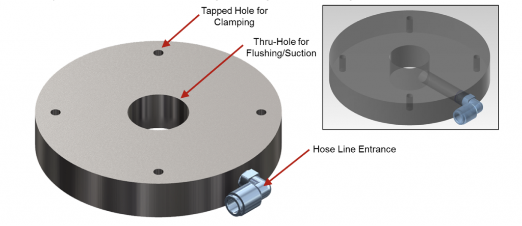
Flushing of Internal or External Gear Forms
The machining of Internal or External Gear Forms will commonly incorporate the use of a Flush Pot or Flushing Manifold to aid in machining. This style of flushing will use an auxiliary flush line from the machine to provide Injection Flush (positive pressure that PUSHES debris away), or Suction Flush (negative pressure that PULLS debris away). Injection Flush is typically preferred and more commonly used, because Suction can sometimes cause a valve component clogging issue if too much debris is introduced into the machine plumbing.
Both Injection and Suction Flush can be utilized in processing gear forms. It’s advantageous to use Injection Flushing during Rough machining and Suction during Finish machining. The benefit to using Suction Flush during Finishing operations is that it helps keep the work piece cleaner, so that there is less potential for any secondary discharge machining from occurring as a result of debris on the part. This can also help improve the surface finish consistency.
Flush Pots and Flush Manifolds are work-holding fixtures that are simple to make and are usually made in-house from a tool steel and customized for a specific job need, such as for the part size and depth requirements. Flush Pots are bolted to the machine table or placed on a magnetic chuck. They’ll contain a series of tapped holes to clamp down the work piece. Flush Manifolds are typically more customized, and can have separate compartments that require different flushing applications.
Flush Pots and Flush Manifolds will both utilize an external source for injection flushing or suction, and this will typically come from the auxiliary ports of the Sinker EDM machine. The flush lines that connect the machine auxiliary ports to the Flush Pot or Manifold will also require an adjustable valve to control and meter the flushing pressure and/or volume. In most applications, the flushing or suction amount needed is small (1 psi or 0.01MPa), and should be set to the lowest level that achieves positive removal of machining debris. If too high a flushing or suction volume is used, it may disrupt and destabilize the EDM process and extend cycle time. Some Sinker EDM machines have options for programmable flushing that provide automatic volume and pressure control, and may include automation for programming and switching multiple flush lines.