This question hits on many areas that relate to the machine as well as CAM system programming techniques. Here are a few items to address and review for best results:
MACHINE ITEMS:
- Maximum Taper Angle: It’s important to identify the maximum taper angle that a 4-Axis program will need to machine. This information can be provided by most CAM systems, or can be established by Dry Running the program on the machine control. The maximum programmed angle will impact which wire type, machining conditions, and machine nozzles are used.
- Wire Type: The type of wire that’s used to perform 4-Axis or Taper machining will affect end results. It’s typically recommended to use a half-hard wire – either straight brass or coated, depending on the specific application and material being cut – when machining taper angles exceeding 10 degrees. These soft/half-hard wires have a tensile strength of 450~500Nm² and are designed for taper applications. They also have a higher elongation rating, making it possible to “stretch” the wire more than a standard hard, high tensile strength wire. Both a lower tensile strength and higher elongation rating make it possible for wire to bend to the proper angle with less resistance. Typical hard brass wire, which has a tensile strength of 900Nm² or more, can result in multiple breaks and excessive wire vibration during high taper machining. This can be seen as visible lines on the completed part.
- Machining Conditions: The selection of Machining Conditions (power settings) also impacts 4-Axis and taper accuracy results. Knowledge of the maximum taper angle is very helpful here, as it provides guidance as to what condition can be used.
Depending on the machine manufacturer, if machining under 10 degrees, typically Standard Conditions (same as for hard brass wire) can be used. This approach will usually favor speed over accuracy, and manual adjustments to wire tension may be required for fine tuning and best accuracy. Too high a tension on the wire during 4-Axis and Taper machining may result in excessive wire breaks and wire lines on the part.
If machining at or over 10 degrees, dedicated taper conditions may be available (again depending on the machine manufacturer).
- Machine Nozzles: It may be necessary to change to different nozzles to accommodate the Maximum Taper Angle. If incorrect nozzles are used, the wire may get in contact with the nozzle, which will result in taper angle inaccuracies.
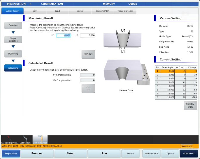
- Taper Calibration: Machine controls can provide a Taper Calibration software function that may be used to verify and fine-tune taper machining accuracy at any required angle. Please review the machine manual for Taper Calibration information and procedures. Below is an example of what this might look like on a machine control screen.
NC PROGRAM (CAM SYSTEM):
- Verify that proper values are used for Taper Planes
- G95 Command Line (G95 P_____ Q_____ Z#5015)
- With 4-Axis programs, the Sub-Plane (Q-Value) MUST be set to the same Z-Height CAD distance between the Upper and Lower profiles used to create the program.
- Proper NC output for 4-Axis machining (P0, P1, P2)
- There are three available modes on the machine for 4-Axis programming which tell the machine how the CAM system has calculated U/V numbers.
- The “P1” designation is the most common, and calculates the U/V positions as INC from the X/Y.
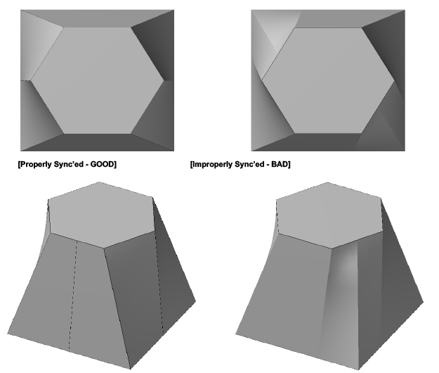
- Proper synchronization of Upper and Lower geometry in CAM system
- When creating a 4-Axis program with different shapes on the Top and Bottom profiles, it may be necessary to properly synchronize and match the profiles.
- If the profiles aren’t matched correctly within the CAM system, the output program may be incorrect and result in unwanted twisted geometry.
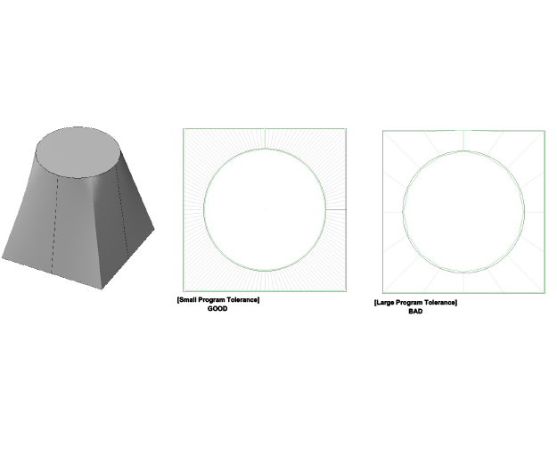
- Proper Tolerance setting within CAM system for 4-Axis output
- Many CAM systems provide a profile tolerance or filter function that can be used to reduce the size of a 4-Axis program.
- If these settings are active and set to large values, the produced 4-Axis geometry may not be accurate and can produce facets or flat lines.
- To ensure best results, it’s recommended to create a larger NC program by turning off any filters, and set any 4-Axis tolerance parameters to 0.001mm or 0.00001” inch.
- Program output options
- G01 Linear (Line) output or G02/G03 (Arc)
- By machine parameter, the 4-Axis program format can be changed to match the CAM system’s post-processor output. The program format will not impact machining speed or accuracy.
- The default and most common 4-Axis format uses all G01 lines (G01 X___ Y___U___V___)
- The machine also can accept G02/G03 4-Axis format (G02 X___Y___I____J____U___V___K___L___)
- Output Offset Geometry
- CAM systems can output modified geometry NC code, so any programmed offsets are built into the values of each program pass.
- G01 Linear (Line) output or G02/G03 (Arc)
4-Axis Programming Pictures: